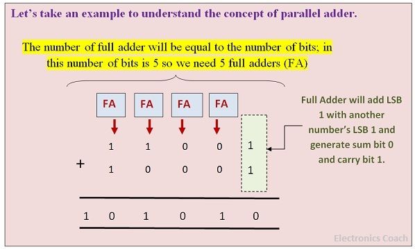
Parallel Adder Circuit Diagram And Truth Table Logic Gates A
Half adder and full adder truth table 4 bit adder subtractor truth table 4 bit parallel adder circuit diagram
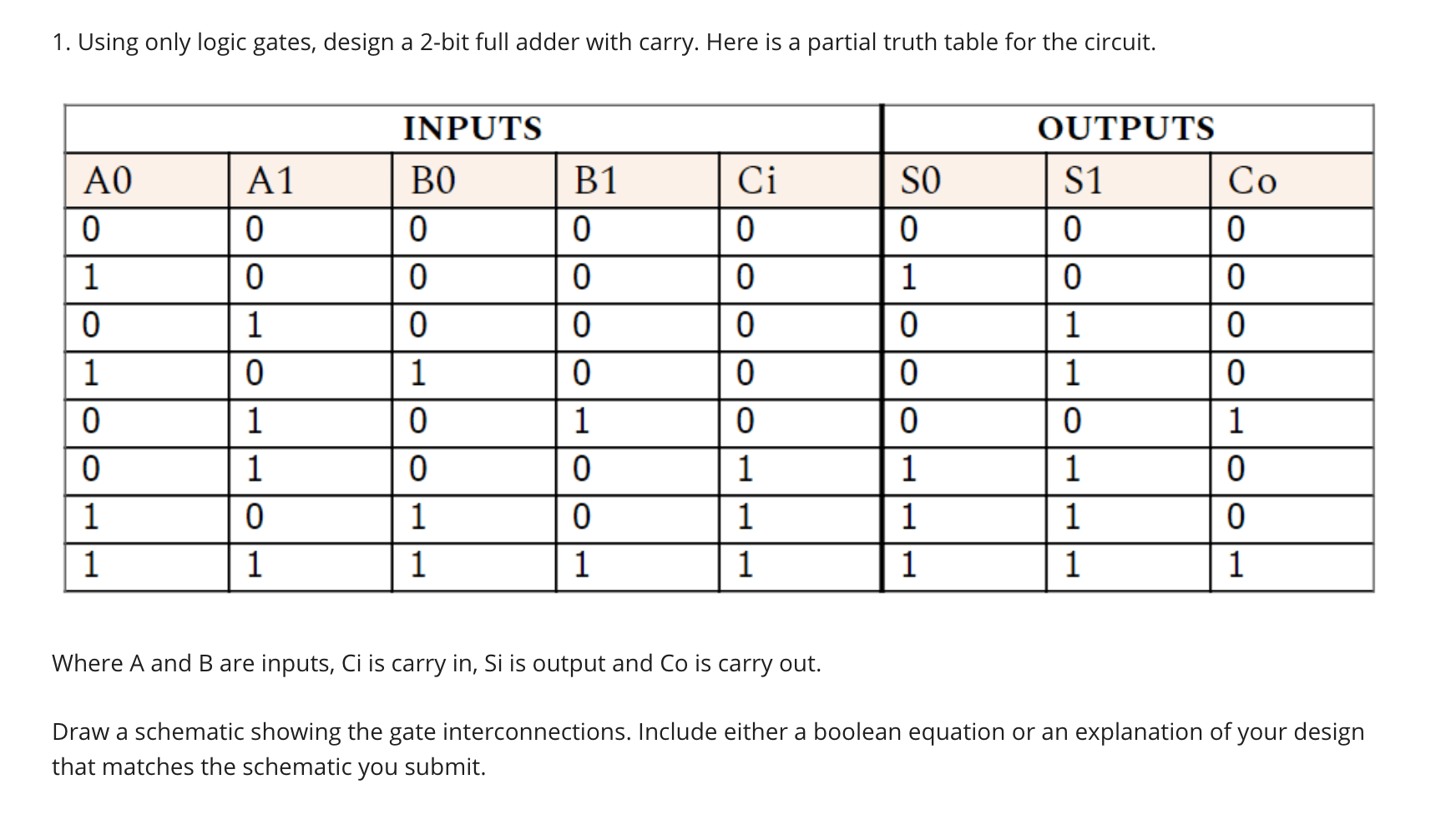
Solved 1. Using only logic gates, design a 2-bit full adder | Chegg.com
Adder bit parallel four truth table circuit diagram binary schematic block 8 bit parallel adder circuit diagram Parallel adder and parallel subtractor
Adder parallel subtractor geeksforgeeks
🎉 4 bit parallel adder theory. 5.9: four. 2022-10-30How to build a full adder circuit Subtractor adder truth table full binary expression boolean half diagram carry output block gate back top along shownAdder logic gates theory calculator binary circuits bits nand.
Logic addition adder gates full circuit binary quantum implement computers ibms performing medium used max computing source4 bit parallel adder circuit diagram Half adder truth table and circuit diagramWhat is parallel binary adder?.
Adder parallel bit binary numbers
Explain 4 bit binary parallel adderBinary adders a binary adder is a digital circuit that performs the 4-bit adder subtractorFrom binary to logic part ii: logic gates.
Solved 1. using only logic gates, design a 2-bit full adderDraw the circuit diagram of full adder with its truth table and working Block diagram of full adder circuit4 bit adder subtractor truth table.

[diagram] bcd adder circuit diagram
Binary adder circuit diagram😊 four bit parallel adder. 4 bit binary adder circuit / block diagram Adder full truth table boolean carry expression electronicspost8 bit parallel adder truth table.
Binary adder and subtractor circuits: half and full adder, subtractorAdder logic block boolean implementation Draw the circuit diagram of full adder with its truth table and working4 bit parallel adder circuit diagram » wiring boards.

Draw the circuit diagram of full adder with its truth table and working
Half adder and full adder circuitLogic gates adder outputs partial transcribed 8 bit full adder truth table[diagram] 4 bit adder logic diagram.
Full adder circuit truth tableFull adder and subtractor circuit diagram Adder half study combinations outputs input correspondingBlock diagram of full adder circuit.
Full adder – electronics post
.
.

Draw The Circuit Diagram Of Full Adder With Its Truth Table And Working

Half adder truth table and circuit diagram - propertylasopa

8 bit full adder truth table - vilaviation

Binary Adders A Binary Adder is a digital circuit that performs the

Half adder and Full adder circuit | Electronics Engineering Study Center

🎉 4 bit parallel adder theory. 5.9: FOUR. 2022-10-30

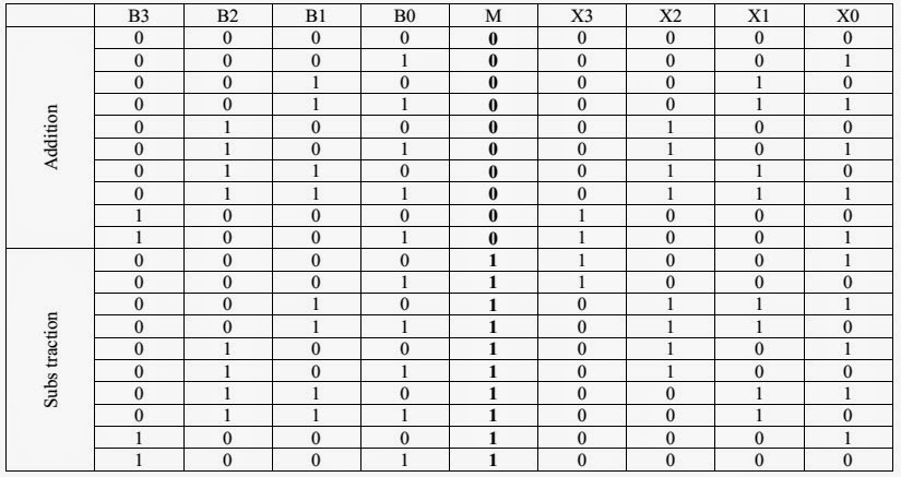
4 Bit Adder Subtractor Truth Table